top of page


HARMONIC FILTERS

Harmonic filters are inductance coils connected in series with compensation capacitors to protect devices and machines operating in the system from the damaging effects of harmonics, using reactive power compensation components.
OMSAN harmonic filters are manufactured under the ISO 9001 quality management system, with CE certification within the scope of EN 61558-2-20.
Causes of Harmonic Distortion:
The source of harmonic distortions in voltage and current (THD) is nonlinear loads. Briefly, these loads include:
-
Uninterruptible power supplies,
-
Motor starters,
-
Motor drivers,
-
Speed controllers,
-
Computer and electronic lighting,
-
Welding machines,
-
Power electronics converters,
-
Rectifiers and similar devices that increase harmonic distortion in the network.
MAIN FAULTS CAUSED BY HARMONIC DISTORTIONS;
-
Heating in electromechanical devices and cables,
-
Mechanical vibrations in machines,
-
Abnormal operation of ignition circuits,
-
Voltage surges,
-
Breakdowns in cables and other electromechanical devices due to high voltage,
-
Faults in electronic boards, devices, and computers,
-
Power losses, bursts, and explosions in power capacitors,
-
Trips in compensation fuses,
-
Unexplained tripping in circuit breakers and switches,
-
Distortion and abnormal operation of relay signals,
-
Energy losses.
BENEFITS OF USING HARMONIC FILTERS;
-
They prevent overloading by reducing voltage and current harmonic values, thus extending the life of compensation capacitors.
-
They reduce the risk of a reactive penalty,
-
They help regain the sinusoidal waveform by reducing elevated system harmonics,
-
They prevent damage to devices and machines used in the facility due to harmonic distortions,
-
They prevent overheating of transformers, cables, busbar systems, and other wound devices,
-
They prevent instantaneous excessive current draw in capacitors,
-
They prevent the compensation system from entering resonance,
-
They prevent fuses from tripping prematurely,
-
They reduce unexplained problems and malfunctions in electronic boards, devices, and computers.
HARMONIC FILTER SELECTION
Harmonic filters are selected according to the mains voltage, frequency, distortion, filtering factor, and the reactive power of the stage to which they will be connected. The resonance frequency should be selected to match the harmonics. When selecting the capacitor voltage, it is necessary to calculate how much the voltage going from the filter to the capacitor will increase according to the filtering factor, and the capacitor voltage should be selected above this value. To avoid causing insufficient compensation power, we must remember that the stage power is equal to the harmonic filter power. The total reactive compensation power must be calculated based on the filter power values .
As filters will cause a rise in temperature within the switchboard, the switchboard’s ventilation system must be reliable and durable. In filtered compensation systems installed to correct harmonic distortion, great care must be taken in the selection of filters and capacitors. The design of harmonic filters is based on factors such as the resonance frequency (typically 134, 189, 210 Hz), capacitor power, and capacitor voltage.
Harmonic filters produce voltages higher than the mains voltage. Considering that voltage levels are higher than normal, especially in organized industrial zones, during the night, ensure that the capacitors installed in the system have high voltage ratings.
Remember that connecting capacitors with voltage and power values different from those required for harmonic filters will cause the system's resonance frequency to shift and performance to decrease. Therefore, be sure to use filters designed according to the power and voltage values of the capacitors.
Harmonic filters cause a temperature increase inside the panel. Therefore, ensure that the panels are designed to provide sufficient airflow.
In compensation systems with harmonic filters, the final power will be different from the sum of the capacitor power values. Therefore, to avoid undercompensation, remember to take harmonic filters into account when calculating the power.
To enable us to respond to your harmonic filter requests, the minimum information you need to provide to our company is:
-
Mains voltage,
-
Resonance frequency (134, 189, 210 Hz),
-
Capacitor power and voltage values,
-
THDU and THDI min.-max. values,
-
Harmonic analysis reports if the harmonic distortion of the energy system is at high levels.
MAGNETIC CORE DESIGN IN HARMONIC FILTERS;
-
In the design of series harmonic filters, the linearity of the magnetic properties is very important. In this context, the magnetic core design of the filter is an important consideration.
-
Any nonlinearity causes the following problems;
-
Increased power losses in areas adjacent to air gaps
-
Increased heat
-
Increased audible noise
THE IMPORTANCE OF MAGNETIC CORE DESIGN;
-
A properly designed magnetic core ensures the following gains:
-
It provides a constant inductance value regardless of wide-range variations in the harmonic filter current (magnetic linearity),
-
It reduces audible noise levels,
-
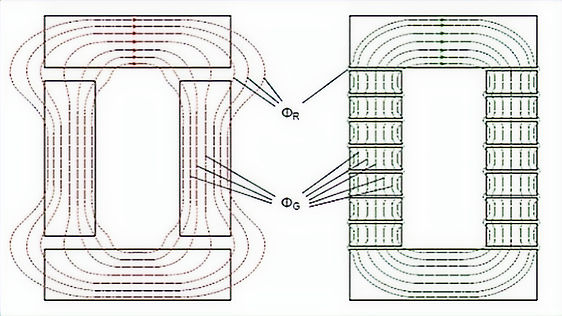
It eliminates the external magnetic field (as shown in the diagrams),
-
It reduces additional losses in the windings and structural elements.
Çapa 1
bottom of page